Dimensioning Sheet Metal Flat Pattern

New To Sheet Metal Looking For Feedback About Dimensioning Autodesk Community Inventor
Sheet Metal Layout Tip Dimension To Formed View Not Flat Pattern

How To Define The Mbd Data Of Sheet Metal Parts Engineers Rule

What Happened To My Flat Pattern View Computer Aided Technology

Solved Sheet Metal Drawings Dimension Problem Autodesk Community Inventor

Drawing The Inventor Flat Pattern
Use k factor calculator to calculate k factor values.
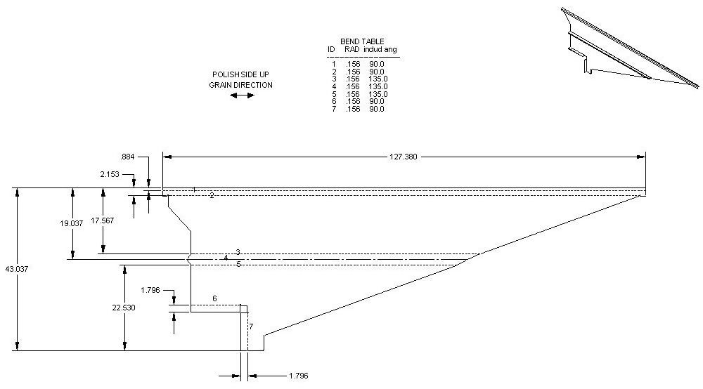
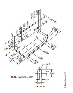
Dimensioning sheet metal flat pattern. I think this is the better way because you can acquire your cutting length without a flat pattern by adding the inside lengths fold allowance. When you expand the representation of a body in the cut list the body s flat pattern appears at the end of its feature list. The flat pattern drawing doesn t always list these factors. When producing drawings of sheet metal components i dimension from inside the flange walls.
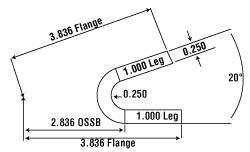
Enter flange length internal radius and thickness values. Value of bend deduction and flat pattern are shown in result section. Keep default values in calculator as zero. Sheet metal flat length can be calculated in the following three simple steps.
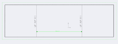
When considering sheet metal thickness a single sheet with punches holes is a good rule of thumb. If the value of sheet metal k factor and bending flange length is known. The flat pattern drawing doesn t always list these factors. And also find you fold centers more easily.
This can be a physical drawing or template or a computer model. Bend allowance ba π 180 r k t a. Dimensions given on a flat pattern are affected by several bending factors like k factor and bend radius during the 3d modeling stage. Generally capabilities of of 0 9mm 20mm in thickness are able to be manufactured from sheet 3mm or plate 3mm but this tolerance depends mainly on the part.
My boss dimensions from outside the flange walls and thinks. Enter k factor values. Calculate the value bend allowance for required sheet metal bend by using below formula. Here are the steps to be followed to calculate sheet metal flat length.
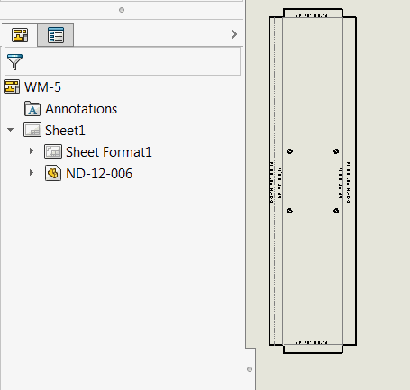
Multibody sheet metal parts. The sketch and locating dimensions are retained. Flat patterns of all bodies appear at the end of the featuremanager design tree.

R11 Flat Pattern Vs Iv2008 Flat Pattern Autodesk Community Inventor

Solved Flat Pattern Dimensions In Parts List Again Autodesk Community Inventor

Standard For Dimensioning Sheet Metal Flat Patterns Induced Info

3d Cad Modeling Of Sheet Metal Parts

Practical Machinist Largest Manufacturing Technology Forum On The Web

Layout And Forming Part One
Solved Instructions 1 From The Selected Sketch Draw The Chegg Com
Fabrication Formulas Sheetmetal Me

Reading Precision Sheet Metal Prints Ppt Download

Seven Improvements For Sheet Metal Drawings Drew Cad Booster

Drafting For Electronics Projection And Dimensioning

Sheet Metal Annotations In Drawings Inventor 2016 Autodesk Knowledge Network

Dimension Flat Sheet Metal Youtube
Sheet Metal Dimensioning Standards
2012 Solidworks Help Creating Drawings Of Sheet Metal Parts
Solved Instructions 1 From The Selected Sketch Draw The Chegg Com
Add Dimensions To Bend Lines Using Solidworks Api

Inventor Sheet Metal Drawings Youtube
Https Encrypted Tbn0 Gstatic Com Images Q Tbn 3aand9gct3zfazig75npdzpw Xd R1gzsyacdxiq4uba7vtl4pdytnncyc Usqp Cau

Sheet Metal Drawing Sheet Sheet Metal Sheet Metal Drawing Drawing Sheet

Solidworks 2015 Bend Lines Youtube
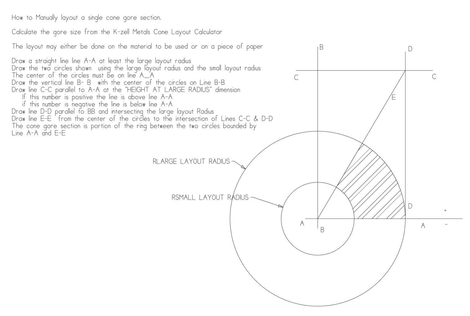
Cone Calculator Sheet Metal Flat Layout Formula K Zell Metals

Add Flat Pattern Dimension For All The Instances At A Time For A Sheet Metal Part In Creo Parametric Youtube
Https Docs Plm Automation Siemens Com Data Services Resources Se 109 Se Help En Us Selfpacedext Pdf Mt01419 Pdf
Https Forums Autodesk Com Autodesk Attachments Autodesk 78 374690 1 Drawing Drafting Modeling Standards And Practices Sheet Metal Pdf

Solidworks Sheet Metal Drawings Youtube
Library Of Macros And Scripts To Automate Solidworks
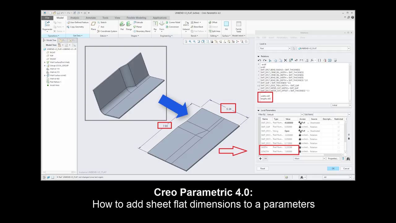
Creo Sheetmetal Tutorial How To Add Sheet Flat Dimensions To A Parameters Youtube

Https Encrypted Tbn0 Gstatic Com Images Q Tbn 3aand9gcr3uegle3co0jbjy6m5r2yxmblik Hbvw1amg Usqp Cau

Sheetmetal Workbench Freecad Documentation

Electronics Drafting Packaging Drawings

Inventor 101 Flat Pattern Dimensions For Use In Drawing Autodesk Community Inventor
The Basics Of Applying Bend Functions

Mid Term Review For Design And Engineering 2 Flashcards Quizlet

College Of San Mateo Official Course Outline Course Id Semester Units Hours

Flat Pattern Length And Width In Parameters Iproperties Autodesk Community
Http Www Ceet Niu Edu Faculty Kim Mee270 Mee270 Ch9 Pdf
Flat Oval Spiral Pipe Fittings Flat Oval Ducts Smc

Geometric Dimensioning And Tolerancing Docsbay
Sheet Metal Design The Definitive Guide Engineer S Handbook Machinemfg

What S New In Autodesk Inventor 2021 Inventor 2021 Autodesk Knowledge Network
Https Www Alibre Com Alibredownloads Alibredesign Exercisemanual Sheetmetal V21 Pdf